Lab 3: Potentiometers
A potentiometer is a type of variable resistor. For the potentiometers in your kit the resistance between the two side pins (A and B in the diagram below) is always 10 kΩ (10,000 Ω). The center pin (C in the diagram below) is electrically connected to a point along the resistor that varies as the knob is turned one way or the other, which in turn varies the resistance between A and C (and B and C).

Example Program
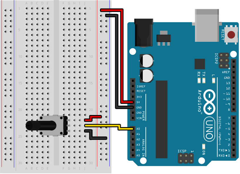
Assemble the following circuit and upload the program to your Arduino:

Before you can connect the potentiometer to your breadboard you will need to bend or remove the two metal tabs on the bottom of the potentiometer so that they do not physically block you from inserting the pins into the breadboard. Although they are not useful for our purposes, these tabs exist so that the potentiometer could be firmly attached to a circuit board.

void setup()
{
    Serial.begin(9600);
    pinMode(A0, INPUT);
}

void loop()
{
    Serial.println(analogRead(A0));
}
If you open the serial monitor in the Arduino IDE you should see a stream of numbers being printed to it, with values between 0 and 1023 that change as you twist the knob from one end to the other.
Learn More
-
When the two side pins of a potentiometer are connected to 5 V and 0 V, this creates a circuit called a voltage divider that causes the voltage on the center pin to vary between 5 V and 0 V as the knob is turned from one end to the other. It is not important to understand why this works (although it has an interesting answer), but know that when a potentiometer is hooked up in this way the voltage on the center pin will follow the position of the knob.
-
In the previous lab we used
digitalRead()to measure a voltage and convert it to eitherHIGHorLOWdepending on if it was closer to 5 V or 0 V. This time we are usinganalogRead()to do the measuring, which has the ability to return a continuous value mapping 0 V to 0 and 5 V to 1023. Although this is not truly “analog” it is much closer, with 10 bits of precision (1024 possible values from 0 V to 5 V) instead of just 1 bit (2 possible values, either 0 V or 5 V). -
Before you use a pin as an analog input by calling
analogRead()you must make sure the pin is configured as anINPUT(and notINPUT_PULLUP) in yoursetup()function. UsingINPUT_PULLUPwill causeanalogRead()to return inaccurate values. -
Not all pins can be used with
analogRead()! If you look back at the table of pin capabilities following Lab 2 you will see that only pins A0 through A5 support theanalogRead()function.
Assignment
Create an “LED bar graph” using at least 4 LEDs (you choose the number and colors) that “fills up” as you turn the potentiometer clockwise. When the potentiometer is turned all the way counter-clockwise all the LEDs should be off, and then as you turn it clockwise they should turn on one by one until the potentiometer is all the way clockwise and all of the LEDs have turned on.
In the previous lab we used an if / else statement to do one of two different things depending on the state of a switch:
if (digitalRead(3) == LOW)
{
    // The switch is on.
}
else
{
    // The switch is off.
}
We can do something similar with the return value of an analogRead() call by using comparison operators like < (less than) and > (greater than). Keeping in mind that the range of values returned by analogRead() is somewhere between 0 and 1023:
if (analogRead(A0) < 512)
{
    // The potentiometer is turned one way.
}
else
{
    // The potentiometer is turned the other way.
}
You can do more complicated things with if and else than merely choose between two options. See the deep dive that follows for examples of more complex usage.