Lab 13: Rotary Encoders
The rotary encoder looks like a potentiometer but is actually digital instead of analog and can be rotated continuously instead of being limited to a small angular range. You can also press it like a button. They are not alike at all!
Example Program
Connect the rotary encoder to your Arduino by making the following connections with the long M-to-F jumper wires included in your kit, and then upload the program to your Arduino:
| Rotary Encoder | Arduino Pin |
|---|---|
| CLK | 3 |
| DT | 2 |
| SW | 4 |
| + | 5V |
| GND | GND |
#include <Encoder.h>

Encoder encoder(2, 3);

void setup()
{
    Serial.begin(9600);
    pinMode(4, INPUT_PULLUP);
}

void loop()
{
    // Reset the rotary encoder’s logical position when clicked:
    if (digitalRead(4) == LOW)
    {
        encoder.write(0);
    }

    Serial.println(encoder.read());
}
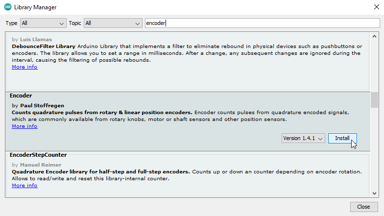
Before you can compile and upload this program to your Arduino you will need to open the library manager in the Arduino IDE (“Tools > Manage Libraries…”, or Ctrl+Shift+I), type “Encoder” into the search bar, and install the “Encoder” library by “Paul Stoffregen”. (See screenshot on next page.)
Once you have installed the library and compiled and uploaded the program you should see a stream of numbers being printed to the serial monitor that increase when you turn the knob clockwise, decrease when you turn the knob counterclockwise, and reset to zero when you push the knob down so that it clicks like a button.

Learn More
-
Similar to the servo motors in Lab 8, using the rotary encoder requires you to put
#include <Encoder.h>at the top of your program and create anEncoderobject, this time specifying the pins that it is connected to (2 and 3) when you declare it. -
By calling the encoder’s
read()function you can get its current position, which changes when it is turned in either direction. -
By calling the encoder’s
write()function you can reset the number that is being adjusted by the knob. Unfortunately, this does not also change the physical position of the knob. -
The rotary encoder conceals a button, much like the buttons in your kit, that connects the “SW” pin to ground when pressed. By connecting this to an I/O pin and configuring it for
INPUT_PULLUPwe can use it as an input, just like we did in Lab 7. -
Although you can technically connect the “DT” and “CLK” pins of the rotary encoder to any two
digitalRead()capable pins on the Arduino, pins 2 and 3 are special in that they support something called hardware interrupts that make the rotary encoder much more responsive and precise when you use those pins specifically. You do not need to understand why, you just need to know that it works!
Assignment
Recreate the circuit from Lab 3 using the rotary encoder instead of a potentiometer. At any given time only a single LED should be on; turning the knob one "click" should light up the previous or next LED in the sequence based on which direction the knob was turned.
When the end of the sequence is reached, turning the knob one "click" further in that direction should “wrap around” and turn on the LED at the opposite end of the sequence, so that the knob can be continuously turned in either direction to repeatedly cycle through the LEDs, with exactly one always being on at any given time. You can accomplish this by using the encoder’s write() function to change the encoder’s value when it goes “out of bounds” on either end.