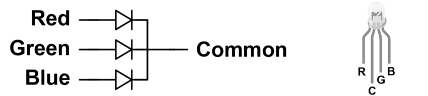
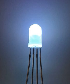
An RGB LED looks a lot like a normal LED, except that it has four pins instead of two. They contain three independent LEDs (red, green, and blue) that can be turned on separately or together to create many different colors, like a pixel on a screen. If you turned on the red and blue LEDs at the same time the light would be magenta. If you turned on all the LEDs at the same time the light would be white. Each LED in the RGB LED is wired separately and needs its own current-limiting resistor to not “burn out.”
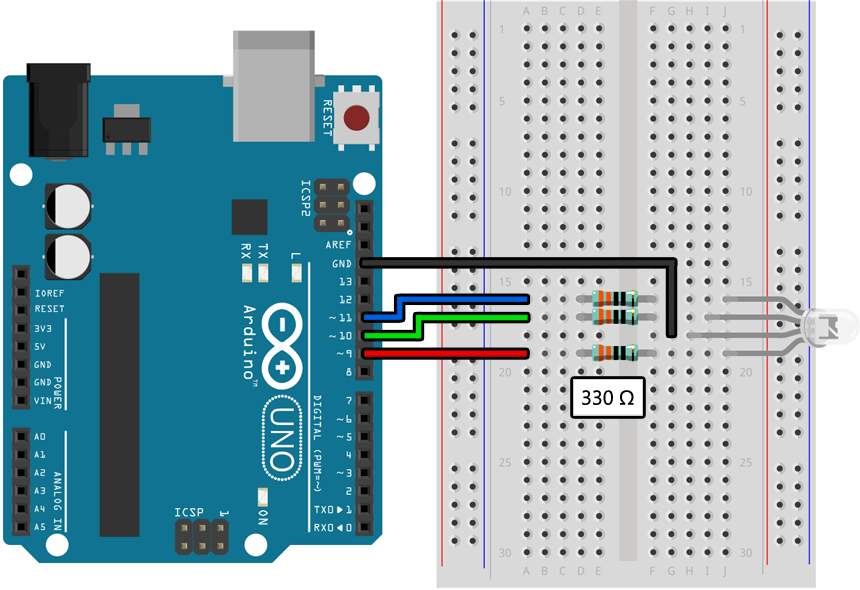
Assemble the following circuit and upload the program to your Arduino:
void setup()
{
    pinMode(9, OUTPUT);     // Red
    pinMode(10, OUTPUT);    // Green
    pinMode(11, OUTPUT);    // Blue
}

void loop()
{
    // Make the LED light up red:
    analogWrite(9, 85);
    delay(200);
    analogWrite(9, 170);
    delay(200);
    analogWrite(9, 255);
    delay(200);
    analogWrite(9, 0);

    // Make the LED light up green:
    analogWrite(10, 85);
    delay(200);
    analogWrite(10, 170);
    delay(200);
    analogWrite(10, 255);
    delay(200);
    analogWrite(10, 0);

    // Make the LED light up blue:
    analogWrite(11, 85);
    delay(200);
    analogWrite(11, 170);
    delay(200);
    analogWrite(11, 255);
    delay(200);
    analogWrite(11, 0);
}
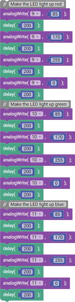
Your RGB LED should alternate between red, green, and blue, each time ramping up linearly from fully off to fully on over about a second. If you are seeing this but with the wrong colors it means you have hooked up the pins in the wrong order; check your wiring and try again.
In previous labs we used digitalWrite() to turn LEDs on and off. In this lab we are using analogWrite() to power LEDs at less than full brightness. Instead of writing HIGH or LOW, we write an integer value between 0 (fully off) and 255 (fully on). In the example above we use it to ramp up the brightness of red, green, and then blue.
Much like analogRead(), the analogWrite() function is particular about pins and can only be used with pins 3, 5, 6, 9, 10, and 11. This is indicated on the Arduino itself by a dot next to the pin number.
Although this lab has you using analogWrite() with RGB LEDs, you can also use analogWrite() with single-color LEDs. In real-world electronics this is a common way to vary the power of analog devices like lights and motors when using a microcontroller.
Although the name of analogWrite() may lead you to believe it is generating an analog value (between 0V and 5V) on an output pin, the microcontroller in your Arduino does not have the ability to do this. What it is really doing is something called pulse-width modulation (or “PWM”) which involves quickly turning the pin on and off while varying the amount of time spent on or off (the duty cycle) depending on the “analog value” written.
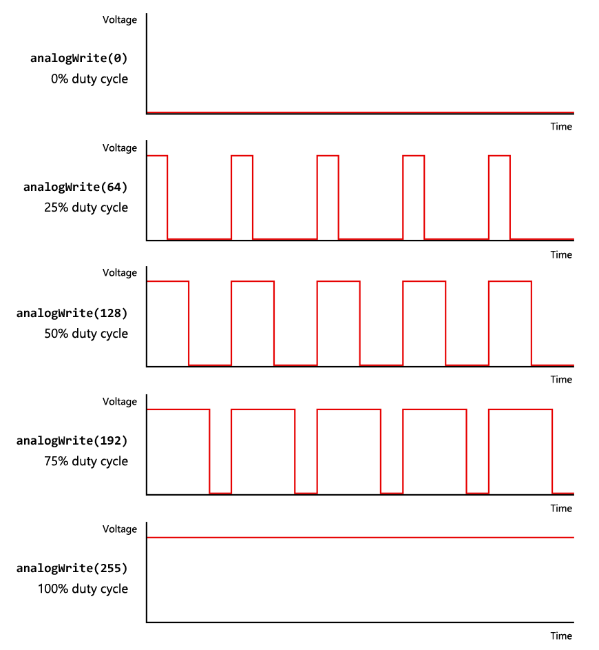
This is very different from a true analog output that can generate any voltage between 0V and 5V, and PWM can not be used in every situation that calls for a proper analog signal. For something like an LED, however, this is perfectly fine; although the LED is technically flashing on and off, it is going so fast that you cannot see it. Instead, you just see the light get brighter or dimmer as the LED spends more or less time turned on.
In the example above we lit up the three colors of the RGB LED separately. You can make many more colors, however, if you turn on more than one color at the same time. This is called additive color mixing. Mixing red and blue makes purple, mixing green and blue makes cyan, and mixing red and green (somewhat unintuitively) makes yellow.
|
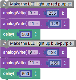
If you vary the intensity of one color relative to another you can further adjust the resulting color:
void setup()
{
    pinMode(9, OUTPUT);     // Red
    pinMode(10, OUTPUT);    // Green
    pinMode(11, OUTPUT);    // Blue
}

void loop()
{
    // Make the LED light up red-purple:
    analogWrite(9, 255);
    analogWrite(11, 128);
    delay(500);

    // Make the LED light up blue-purple:
    analogWrite(9, 128);
    analogWrite(11, 255);
    delay(500);
}
Create a circuit that blends the output of an RGB LED between two different colors as a potentiometer is turned from one end to the other. You can choose whatever colors you want, but they need to be distinct enough that the color blending is clearly visible.
For a harder challenge, try to make it blend over the full range of colors in the visible light spectrum.
For an even harder challenge, try hooking up a second potentiometer and using it to vary the brightness of the RGB LED between 0% and 100%, regardless of the color chosen by the first potentiometer.